Shoreline Mapping History
T-sheets and Nautical Charts | Aerial Imagery | Lidar | Satellite Imagery
T-sheets and Nautical Charts
 In the early 19th century, shipping between the states took place along the coast because land transportation was often difficult. Essential foreign trade, correspondence, and diplomatic forays to Europe, too, were accomplished by sea, and commercial fishing was a large industry. This reliance on ships and the sea sparked a need for a comprehensive effort to survey our coastal waters and publish the findings.
The coastal mapping effort grew as new territories were claimed and as shipping traffic increased with the discovery of gold in California and Alaska. The Survey of the Coast was founded to create "an accurate chart of every part of the coasts." Each chart would be built from two types of surveys. The first was a nautical (or hydrographic) survey, which mapped the depths of coastal waters and offshore hazards. The other was a topographic survey, which mapped the land, including the shoreline, natural and cultural features, and elevations above the sea.
Later the Survey of the Coast became known as the U.S. Coast Survey. The U.S. Coast Survey became responsible for charting over 3.4 million square nautical miles of water and 95,000 miles of shoreline, as well as alerting mariners to the depths and dangers along the 200-mile zone adjacent to the U.S. coastline, an area known as the Exclusive Economic Zone.
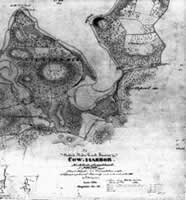
The U.S. Coast Survey created its first topographic map in 1834. At a scale of 1:10,000 (or about 6.3 inches to one mile), the map covered the shore of Great South Bay on Long Island, New York, between the towns of Babylon and Patchogue. Coast Survey topographic maps eventually became known as topographic sheets, or "T-sheets." Georeferenced T-sheets can now be accessed through the NOAA Historical Shoreline Survey Viewer.
Aerial Imagery
 By the late 1800s, photography was recognized as a useful tool for mapping. The then-named U.S. Coast and Geodetic Survey (C&GS) first used a surveying camera with a plane table for mapping the international boundary between Alaska and Canada in 1894. This use of ground photos for mapping continued through the early 20th century.
By the turn of the century, aerial cameras with multiple lenses, and thus a much wider field of view, were developed in Europe. When these cameras were used with airships (dirigible balloons), survey photographs could cover broad areas.
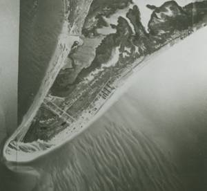
Once the airplane was invented in the early 1900s, aerial photography had a new and ideal platform. The first C&GS aerial photographic mission took place along the New Jersey coast, near Atlantic City, in 1919.
During World War I, the airplane proved to be useful for both combat and photo reconnaissance, and shortly after the war, C&GS became interested in using the airplane for mapping.
In 1919, C&GS started work with the U.S. Army Air Service to investigate using aerial photographs to compile coastal topography. The Air Service provided the aircraft, pilots, cameras, photographers, and developing services. The first project covered the area around Atlantic City, New Jersey.
Early air photo projects used single-lens cameras. These cameras were simple to operate and produced good pictures, but they had very narrow fields of view that required many photographs to cover a moderately sized area. In 1935, C&GS built a precision nine-lens mapping camera. A multi-lens camera could take several photos looking down toward the ground at different angles. For the next 25 years, the C&GS nine-lens camera provided extensive aerial photo survey capability.
Color and Infrared Aerial Imagery
During the 1950s, aerial cameras capable of taking color photographs were introduced. Color photographs were more natural looking than black and white photos, which made the identification and interpretation of various features in the image much easier. With the appropriate filters, color photography could also show underwater features more clearly, making it possible to identify and map submerged rocks, reefs, and shallow areas.
These new cameras were also able to capture near-infrared (IR) light. In black and white, IR photographs show a sharp contrast between land and water, making it easier to accurately identify and map the shoreline in the photograph.
Nautical charts depict the shoreline during mean high water (MHW), which is the average height of all high tides measured over many years. To accurately map the MHW line from IR photography, photos had to be taken during high tide. The first tide-coordinated IR photography for coastal mapping was obtained over Cobscook Bay, Maine, in 1956.
Digital Aerial Imagery
Digital cameras are replacing film-based cameras. Digital aerial cameras increase the speed of availability of aerial photographs. Because images captured by these cameras are already in electronic form, they can quickly be processed and made available to users. The greatest time savings with these cameras comes from their direct georeferencing capability, which allows camera position and orientation to be determined automatically using Global Positioning System (GPS) and inertial measurement unit (IMU) technology. Digital aerial cameras also provide imagery that is more sensitive to shadows and low illumination levels than film photography, and digital cameras typically acquire data in both visible and near-infrared bands. The improved radiometric performance of digital cameras enables significantly better accuracy of image classification.
Lidar
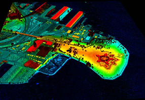
 Light detection and ranging (lidar) is an active remote sensing system that can be operated in either a profiling or scanning mode using pulses of light to illuminate the terrain. Development of lidar technologies began in the late 1960s and became available for commercial topographic mapping in 1993. NOAA, in collaboration with NASA and the U.S. Geological Survey (USGS), has been mapping the shoreline using lidar since 1996 and continues to do so as technological advances in lidar mapping evolve.
Lidar data collection involves mounting an airborne laser scanning system onboard an aircraft, along with a kinematic Global Positioning System (GPS) receiver to locate an x, y, z position and an inertial navigation system to monitor the pitch, roll, and heading of the aircraft. By accurately measuring the round-trip travel time of the laser pulse from the aircraft to the ground, a highly accurate spot elevation can be calculated. Depending on the altitude and speed of the aircraft, along with the laser repetition rate, it is possible to obtain point densities that would likely take months to collect using traditional ground survey methods. The National Geodetic Survey (NGS) is currently implementing lidar into their shoreline mapping production process.
Satellite Imagery
For over 30 years, scientists have utilized satellite imagery for topographic mapping. The Coast and Shoreline Change Analysis Program, a special NGS project, analyzes shoreline changes by comparing recent high-resolution satellite imagery or high-altitude reconnaissance aerial photography with existing NOAA nautical charts. By digitally overlaying the satellite imagery on the charts, changes in shoreline features (piers, bulkheads, shoreline configuration, jetties, groins, etc.) can be easily detected. These detected shoreline changes aid in updating nautical charts.